Next: Bibliography
Up: Interconnect-aware Low Power High-level
Previous: Acknowledgments
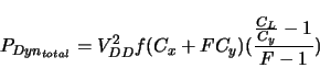
The fixed-taper buffer structure [64] is commonly
used for output buffer design. It consists of a series of
inverters, in which each inverter is larger than its upstream
neighbor by the same factor. From [59], the dynamic
power dissipation of the entire tapered buffer system is
where  is the supply voltage,
  the frequency,
  the
output diffusion capacitance of the first inverter,
the
output diffusion capacitance of the first inverter,  the
input gate capacitance of the first inverter,
the
input gate capacitance of the first inverter,  the fixed taper
factor, and
the fixed taper
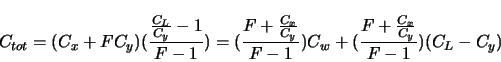
factor, and  the load capacitance. consists of two
components,
the load capacitance. consists of two
components,  , the downstream gate input capacitance which is
the real load, and
, the downstream gate input capacitance which is
the real load, and  , the capacitance of the wire connecting
the driver and the load. Then the total capacitance is
, the capacitance of the wire connecting
the driver and the load. Then the total capacitance is
The second term on the right is independent of the interconnect.
It can be incorporated into the input capacitance of the
corresponding downstream DPU(s). The power consumption due to it
can be taken into consideration by the DPU's power model.
Therefore, we only need to worry about the first term when
computing interconnect-related power consumption. is equal to
![$\sqrt[N]{C_L/C_y}$](img139.png) , where
, where  is the number of inverters in the
buffer, or, stages in the buffer. For power-delay product minimum
buffers, ranges from
is the number of inverters in the
buffer, or, stages in the buffer. For power-delay product minimum
buffers, ranges from  to
to  [65].
is usually smaller than . Thus, we can estimate the
interconnect-related equivalent capacitance of the buffer,
[65].
is usually smaller than . Thus, we can estimate the
interconnect-related equivalent capacitance of the buffer,
 , as
, as  to
to  times the wire capacitance
. In our estimation, we assume
times the wire capacitance
. In our estimation, we assume
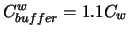 .
Hence, the interconnect-related dynamic power dissipation of the
buffer is about times that of the metal wire.
.
Hence, the interconnect-related dynamic power dissipation of the
buffer is about times that of the metal wire.
Next: Bibliography
Up: Interconnect-aware Low Power High-level
Previous: Acknowledgments
Lin Zhong
2003-10-11